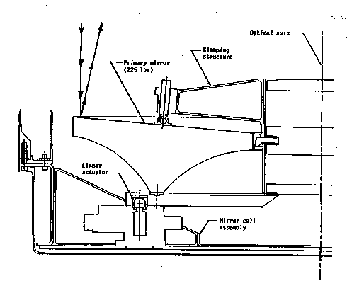
For the Astro-1 flight, the primary mirror was made
of Zerodur, which has a very low thermal expansion
coefficient (![]() ). It is a 90 cm
f/2 parabola that has been lightweighted by grinding material off the back. A cross section of the mirror is shown in
Figure 2-3. The mirror was figured to provide 90
). It is a 90 cm
f/2 parabola that has been lightweighted by grinding material off the back. A cross section of the mirror is shown in
Figure 2-3. The mirror was figured to provide 90![]() of the encircled energy
within 1
of the encircled energy
within 1![]() and was coated with iridium for high reflectivity in the
ultraviolet. It is supported in the primary mirror cell by a clamping
structure as shown in
Figures 2-2 and 2-3. The mirror clamp is then attached
to the mirror cell by three linear actuators (called the focus mechanisms)
that can be used to focus and align the HUT optics. The mirror cell, the
mirror clamp, and the focus mechanisms are all made of INVAR which also has a
low thermal expansion coefficient
(
and was coated with iridium for high reflectivity in the
ultraviolet. It is supported in the primary mirror cell by a clamping
structure as shown in
Figures 2-2 and 2-3. The mirror clamp is then attached
to the mirror cell by three linear actuators (called the focus mechanisms)
that can be used to focus and align the HUT optics. The mirror cell, the
mirror clamp, and the focus mechanisms are all made of INVAR which also has a
low thermal expansion coefficient
(![]() ).
).
 |
For Astro-2, the far-UV throughput of the telescope has been significantly
improved by using a Cer-Vit mirror coated with silicon carbide over iridium.
The physical characteristics of this mirror (which was the backup mirror for
Astro-1) are nearly identical to the original flight mirror, but the SiC
coating placed over the iridium improves the far-UV reflectivity by a factor
of ![]() . Unfortunately, the EUV response below 600 Å is considerably
less.
. Unfortunately, the EUV response below 600 Å is considerably
less.
If needed, the HUT primary mirror can be tilted to achieve co-alignment
with the WUPPE experiment or for observing offset positions up to
![]() 2
2![]() away. Normally, the WUPPE secondary mirror will be
tilted for co-alignment, since the off-axis optical aberrations are less severe
for WUPPE than for HUT. To focus or align HUT, the primary mirror along with
its clamping structure can be moved, as a whole, fore and aft along the optical
axis, or tilted. Each of the focus mechanisms is powered individually by a
motor which drives a linear actuator fixed to the primary mirror clamp
assembly. A single 400 Hz inverter, located in the EM, drives all the HUT
mechanisms and can operate up to three at the same time if they are moving in
the same direction (forward or reverse). The linear actuation of the focus
mechanisms is accomplished by a differential screw assembly.
away. Normally, the WUPPE secondary mirror will be
tilted for co-alignment, since the off-axis optical aberrations are less severe
for WUPPE than for HUT. To focus or align HUT, the primary mirror along with
its clamping structure can be moved, as a whole, fore and aft along the optical
axis, or tilted. Each of the focus mechanisms is powered individually by a
motor which drives a linear actuator fixed to the primary mirror clamp
assembly. A single 400 Hz inverter, located in the EM, drives all the HUT
mechanisms and can operate up to three at the same time if they are moving in
the same direction (forward or reverse). The linear actuation of the focus
mechanisms is accomplished by a differential screw assembly.
Control of the motors is furnished by the DEP, which is located in the EM.
Position sensing potentiometers mounted on the gears of the differential
screw mechanisms provide the DEP with the position of each mechanism. The
software provides for various modes of mirror motion, all of which rely on a
calculation of the run-time for each motor to accomplish a given motion.
When a commanded motion is completed, the potentiometers are checked to
determine
if the correct position has been reached. An error message is issued if any
one of the mechanisms is off by more than a preset lower limit (4 ![]() m).
m).
Using a stellar image placed near the center of the HUT TV camera, the crew will focus the telescope by commanding the primary mirror to move fore and aft. The mirror can also be automatically offset, scanned, or rastered during an observation by placing the necessary information in a sequence file. The observation sequence files will be discussed later.