


Next: 8.2.2 Application of the
Up: 8.2 Low-Dispersion Wavelength Calibration
Previous: 8.2 Low-Dispersion Wavelength Calibration
Each set of calibration images is processed to provide analytic
relations between wavelength and pixel position in low-dispersion SI
space. The derivation of these dispersion relations is a multi-step
process. First, the pixel locations of the Pt-Ne emission lines in a
reference low-dispersion WAVECAL image are measured interactively and
combined with laboratory values for the wavelength of each emission line
(stored in a line library). This analysis is performed using the IRAF
task identify which generates a dispersion solution that is a
one-dimensional fitted function (Chebyshev polynomial) of wavelength
versus pixel number. The next step involves the use of the IRAF task
reidentify which maps the reference-image Chebyshev solution
derived from the identify step to an ensemble of images. The final
dispersion solution is averaged from several hundred individual
solutions output from reidentify and consists of a starting
wavelength and wavelength increment per pixel. The line libraries are
based on the Pt-Ne line positions measured by Reader et al., (1990) at
the National Institute of Standards and Technology (NIST).
Figure 8.1 shows low-dispersion WAVECAL spectra for the
LWP/LWR and SWP cameras and indicates the features included in the
low-dispersion libraries. Table 8.1 contains listings of the
low-dispersion line libraries. The line positions for all cameras, and
therefore the dispersion solutions, are expressed in vacuum
wavelengths.
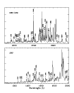 Figure 8.1:
Short and long wavelength low-dispersion
WAVECAL spectra. Pt-Ne features included in the low-dispersion line
libraries are marked.
Figure 8.1:
Short and long wavelength low-dispersion
WAVECAL spectra. Pt-Ne features included in the low-dispersion line
libraries are marked.
Table 8.1:
Low-Dispersion Pt-Ne Line Libraries
| Short Wavelength |
Long Wavelength |
| Camera (Å) |
Cameras (Å) |
| 1248.61 |
1913.23 |
| 1289.95 |
1990.58 |
| 1302.79 |
2037.12 |
| 1380.49 |
2050.05 |
| 1403.90 |
2085.26 |
| 1429.52 |
2129.31 |
| 1482.83 |
2144.92 |
| 1509.29 |
2263.42 |
| 1524.73 |
2357.83 |
| 1574.31 |
2440.80 |
| 1604.01 |
2468.15 |
| 1621.65 |
2487.92 |
| 1669.23 |
2539.97 |
| 1723.13 |
2677.94 |
| 1736.52 |
2734.77 |
| 1753.83 |
2772.48 |
| 1802.94 |
2792.84 |
| 1971.54 |
2831.13 |
| 1990.58 |
2876.48 |
| |
2930.65 |
| |
3094.90 |
| |
3140.30 |
| |
3219.12 |
| |
3324.69 |
| |
3346.42 |
Because the geometric correction and resampling step of the image
processing rotates the low-dispersion images so that the dispersion
direction is parallel to the horizontal or x-axis of the
low-dispersion SI, the terms of the dispersion solutions for the two
image dimensions are completely decoupled. The parameterization of the
dispersion solutions is as follows:
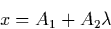
y = B1
where x and y are the image pixel locations and A1, A2, and
B1 are the dispersion constants. For a low-dispersion SI, the y
dimension of the image contains spatial information only. In this case
the B1 coefficient simply gives the image line number at which the
spectrum centroid is located.
Next: 8.2.2 Application of the
Up: 8.2 Low-Dispersion Wavelength Calibration
Previous: 8.2 Low-Dispersion Wavelength Calibration
Karen Levay
12/4/1997
 Figure 8.1:
Short and long wavelength low-dispersion
WAVECAL spectra. Pt-Ne features included in the low-dispersion line
libraries are marked.
Figure 8.1:
Short and long wavelength low-dispersion
WAVECAL spectra. Pt-Ne features included in the low-dispersion line
libraries are marked.