


 Follow Us
|
|

The Berkeley Spectrometer for ORFEUS: Laboratory and In-Flight Performance
MARK HURWITZ AND STUART BOWYER
Center for EUV Astrophysics, 2150 Kittredge Street, University of California, Berkeley, CA 94720-5030, USA
The Berkeley spectrometer aboard the ORFEUS payload achieved a
variety of "firsts" during its inaugural mission in September 1993. The
instrument utilizes spherical gratings with mechanically ruled varied
line-spacing, and curved microchannel plate detectors with delay-line
anode readout systems, to cover the 390 - 1200 Å band at a
resolution of
![]() /5000. The instrument will be discussed, and its
performance illustrated with calibration and in-flight spectra. Science
highlights from the ORFEUS-1 mission will be presented (oral
presentation only). The payload will be available for use by guest
investigators during the ORFEUS-11 mission currently scheduled for late
1996.
/5000. The instrument will be discussed, and its
performance illustrated with calibration and in-flight spectra. Science
highlights from the ORFEUS-1 mission will be presented (oral
presentation only). The payload will be available for use by guest
investigators during the ORFEUS-11 mission currently scheduled for late
1996.
1. Introduction and Background
ORFEUS, the Orbiting Retrievable Far and Extreme Ultraviolet Spectrometers, is a joint project of NASA and DARA, the German space agency. It is an outgrowth of a longstanding collaboration between Prof. Bowyer and the Space Astrophysics Group at UC Berkeley, and Prof. Grewing and the Astronomical Institute at the University of Tuebingen (AIT).
The ORFEUS telescope is 1 meter in diameter
and 4 meters long (Grewing et al. 1991). The Berkeley spectrometer
(Hurwitz & Bowyer 1991) sits at the prime focus of the f/2.4
normal incidence primary mirror. This instrument is designed to
provide high-resolution (![]() /5000) spectroscopy of point sources between 390 and
1200 Å, with an effective area of about 4 - 6 cm2. Alternatively, an
off-axis paraboloidal mirror can be driven into the light path,
collimating the beam and directing it into an Echelle spectrometer
provided by AIT and the Landessternwarte Heidelberg (LSW). That
instrument is designed to provide
/5000) spectroscopy of point sources between 390 and
1200 Å, with an effective area of about 4 - 6 cm2. Alternatively, an
off-axis paraboloidal mirror can be driven into the light path,
collimating the beam and directing it into an Echelle spectrometer
provided by AIT and the Landessternwarte Heidelberg (LSW). That
instrument is designed to provide
![]() /10,000
spectroscopy of point
sources between 900 and 1250 Å at somewhat lower sensitivity.
/10,000
spectroscopy of point
sources between 900 and 1250 Å at somewhat lower sensitivity.
The resolution of the ORFEUS spectrometers, significantly
exceeds that of other instruments with comparable sensitivity at
wavelengths of overlap. Below 760 Å, the spectrometers on the
Extreme Ultraviolet Explorer offer somewhat lower sensitivity
(but longer observing times), and a resolution of ![]() /300. Between 800 and 1250
Å, the Hopkins Ultraviolet Telescope offers higher
sensitivity, and comparable observing times, but again the resolution
is limited to about
/300. Between 800 and 1250
Å, the Hopkins Ultraviolet Telescope offers higher
sensitivity, and comparable observing times, but again the resolution
is limited to about
![]() /300.
The Hubble Space Telescope exceeds ORFEUS
performance above about 1170 Å. A smaller telescope mounted parallel to
the ORFEUS optical axis is IMAPS, (Jenkins et al. 1988) provided by the
Princeton University Observatory. IMAPS offers extremely high
resolution
(
/300.
The Hubble Space Telescope exceeds ORFEUS
performance above about 1170 Å. A smaller telescope mounted parallel to
the ORFEUS optical axis is IMAPS, (Jenkins et al. 1988) provided by the
Princeton University Observatory. IMAPS offers extremely high
resolution
(![]() /2 x 105)
in the far ultraviolet (FUV), but more limited
sensitivity.
/2 x 105)
in the far ultraviolet (FUV), but more limited
sensitivity.
ORFEUS flew successfully aboard the German space platform ASTRO-SPAS, which was deployed from the shuttle Discovery in September of 1993 and recaptured some 5 days later. During this inaugural mission (hereafter ORFEUS-SPAS), the Berkeley spectrometer functioned well. More than 100 individual paintings were successfully carried out with the Berkeley spectrometer, including multiple observations of faint sources. This total includes targets observed for the Berkeley science program, targets observed for our collaborators at AIT and LSW, and joint target observations.
The spacecraft has flown once since the ORFEUS-SPAS I mission, carrying a cryogenic infrared instrument for study of Earth's atmosphere (CRISTA-SPAS). A reflight of the ORFEUS instrument package is scheduled for late 1996. During this mission 50% of the available science time will be devoted to observations led by guest investigators, who may elect to utilize either of the ORFEUS spectrometers or IMAPS. In this paper we discuss the performance of the Berkeley spectrometer in detail. The spacecraft and telescope are discussed insofar as they affect the spectra and the observing program.
2. The Berkeley Spectrometer: General Principles and Design Details
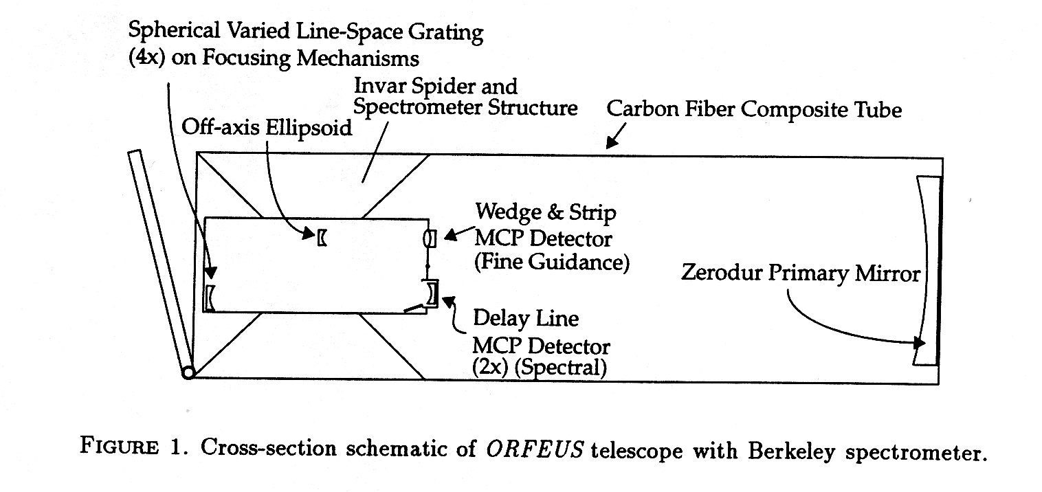 In Figure 1 we show the position of the Berkeley spectrometer
within the ORFEUS telescope (the Echelle spectrometer is omitted for
clarity). The Berkeley spectrometer occupies the inner 50% of the
aperture diameter and obscures the inner 25% of the primary mirror
area. For reference, the instrument Z axis is parallel to the optical
axis; the prime focus defines the plane of Z = 0, and the Z coordinate
increases toward the top of the telescope.
In Figure 1 we show the position of the Berkeley spectrometer
within the ORFEUS telescope (the Echelle spectrometer is omitted for
clarity). The Berkeley spectrometer occupies the inner 50% of the
aperture diameter and obscures the inner 25% of the primary mirror
area. For reference, the instrument Z axis is parallel to the optical
axis; the prime focus defines the plane of Z = 0, and the Z coordinate
increases toward the top of the telescope.
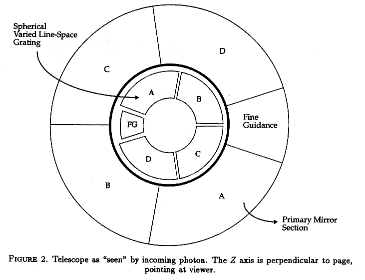 Shadows from five spider
vanes divide the monolithic telescope aperture into five segments of
the outer annulus. This segmentation is illustrated in Figure 2, where
we show an incoming "photon's view" of the system. Starlight from all
five segments comes to a common focus some 240 cm from the primary
mirror, then diverges into the Berkeley spectrometer volume.
Shadows from five spider
vanes divide the monolithic telescope aperture into five segments of
the outer annulus. This segmentation is illustrated in Figure 2, where
we show an incoming "photon's view" of the system. Starlight from all
five segments comes to a common focus some 240 cm from the primary
mirror, then diverges into the Berkeley spectrometer volume.
As the beams from the five segments diverge, each segment of the annulus strikes a distinct optic within the Berkeley spectrometer. The smallest segment, representing a 36° wedge of the annulus, is intercepted by an off-axis ellipsoidal optic near Z = +60 cm which images the target and aperture onto a sealed tube microchannel plate detector sensitive to wavelengths near 1500 Å. This fine guidance system is used for initial coalignment of the ORFEUS telescope and the external star tracker of the ASTRO-SPAS. It can also be used for postflight spectral reconstruction to correct for target "jitter" during an observation, although this was not necessary for spectra collected during the ORFEUS-SPAS I mission.
 Each of the larger segments labeled A through D
subtends 81° of the annulus and strikes a distinct diffraction grating.
The gratings are located at the extreme end of the spectrometer, near Z
= +100 cm. The position of the gratings is shown in Figure 2; from
this vantage point the viewer is seeing the "back side" of each
grating, and of course, in the actual instrument the gratings are
obscured by the surrounding spectrometer structure, thermal blankets,
etc. Each grating disperses a unique sub-bandpass across one of two
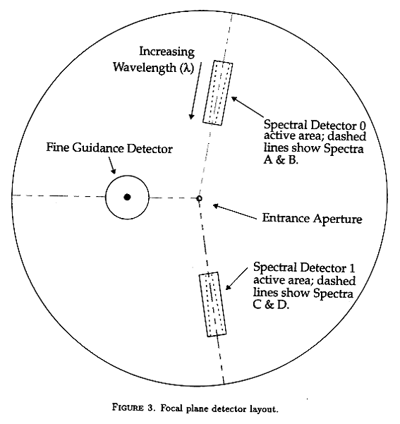
spectral detectors near the focal plane of the spectrometer. In
Figure 3 we show the layout of detectors, including both the spectral and the
fine guidance sealed tube, in the focal plane near Z = 0. Note that the
scale has been expanded by a factor of 2 in this figure.
Each of the larger segments labeled A through D
subtends 81° of the annulus and strikes a distinct diffraction grating.
The gratings are located at the extreme end of the spectrometer, near Z
= +100 cm. The position of the gratings is shown in Figure 2; from
this vantage point the viewer is seeing the "back side" of each
grating, and of course, in the actual instrument the gratings are
obscured by the surrounding spectrometer structure, thermal blankets,
etc. Each grating disperses a unique sub-bandpass across one of two
spectral detectors near the focal plane of the spectrometer. In
Figure 3 we show the layout of detectors, including both the spectral and the
fine guidance sealed tube, in the focal plane near Z = 0. Note that the
scale has been expanded by a factor of 2 in this figure.
The reasons for adopting this overall design are fairly straightforward and are discussed in Hurwitz & Bowyer (1986). The telescope diameter and overall length are the maximum that can be accommodated within the spacecraft and shuttle envelope; a fast primary was a necessity. High-resolution spectroscopy required that either the aperture be subdivided into slower segments, or that a secondary mirror be introduced. The latter would have increased the effective focal length, imposing more severe restrictions on allowable spacecraft jitter. Furthermore, the potential gain in effective area (e.g., utilizing the entire beam vs. only a segment of it) would have been offset by the low reflectivity of normal incidence optics at EUV/FUV wavelengths. And as a practical matter the beam would have required subsequent subdivision in any case, given the very broad spectral bandpass (a factor of 3 in wavelength), the high spectral resolution that was desired, and the limited number of resolution elements provided by even the most advanced detector systems.
The geometry of each grating/detector system is identical save for
rotation about the Z axis and/or reflection through the detector
midplane. The incidence angle is 12°. Central groove densities,
nominal
bandpasses, and coatings are contained in Table 1. The wavelength
coverage
(![]() max/
max/![]() min) of each grating is identical, as is the ratio
of central wavelength to groove density.
min) of each grating is identical, as is the ratio
of central wavelength to groove density.
| TABLE 1. | ||||
|---|---|---|---|---|
| Grating | Central groove dens. (/mm) |
Nom.Bandpass (Å) |
Coating (First Mission) (Second Mission) |
|
| A | 6000.0 | 389 - 523 | Evaporated Ir | Evaporated Ir |
| B | 4550.0 | 513 - 690 | Evaporated Ir | Evaporated Ir |
| C | 3450.4 | 676 - 910 | Evaporated Ir | Sputtered SiC |
| D | 2616.6 | 892 - 1200 | Evaporated Ir | Sputtered SiC |
When the design was first proposed, (e.g., Hurwitz & Bowyer 1986) the optics were toroidal in surface figure, with uniform line spacing, and followed the classical Rowland circle geometry. It was subsequently realized that higher resolution and reduction of astigmatism was possible using spherical optics with mechanically ruled varied line-spacing (SVLS) in a non-Rowland mounting (Harada et al. 1991). Spectrometers of this type had been proposed earlier (Harada & Kita 1980) but had never before been used in an astronomical application. The geometry enforced by the prime focus spectrograph position imposed unique constraints on the optical design. The adopted SVLS parameters, discussed in Harada et al. (1991), were optimized at Berkeley with an iterative raytracing technique.
The two spectral detectors incorporate curved microchannel plates
with delay-line anodes (Siegmund et al. 1991) to encode the X position
of the dispersed photons. ORFEUS-SPAS I was the first space flight for
detectors of this type, and they performed extraordinarily well. Along
the Y axis, imaging is used only to separate the two spectra and to
isolate the spectra from detector background; resolution requirements
are modest. Y-axis imaging is provided by an interleaved wedge/wedge
anode pattern and charge division. Spectral detector parameters are
contained in ![]() able 2. Both spectral detectors are housed in a sealed
vacuum chamber equipped with doors; both utilize KBr photo-cathodes
deposited on the front microchannel plate surface.
able 2. Both spectral detectors are housed in a sealed
vacuum chamber equipped with doors; both utilize KBr photo-cathodes
deposited on the front microchannel plate surface.
| TABLE 2. | ||||
|---|---|---|---|---|
| Dim. | Technique | Length (mm) | Resolution (µm) | Digitization (µm) |
| X | Delay line | 82 | 30 - 40 | 3.5 |
| Y | Chg. division | 26 | 200 | 120 |
We now present relevant characteristics of other hardware systems before returning to system performance values.
3. Spacecraft, Telescope, and Apertures
The ASTRO-SPAS, fabricated by Daimler-Benz Aerospace (formerly Deutsche Aerospace) offers high scientific performance, but its resources are designed for short duration missions.
Absolute pointing is accurate to within a few arc seconds; compressed gas thrusters provide the necessary torques. An external star tracker provides a reference signal to the attitude/maneuvering control system (AMCS). During ORFEUS-SPAS 1, the AMCS successfully placed almost every target within the 20" diameter aperture; one or two observations failed because of a lack of suitable guide stars.
Some tons of watts of power are provided to the experiments, using energy stored in batteries. Data are primarily archived by on-board tape recorders; about 130 kbits s-1 are allocated to the scientific experiments. This high speed (HS) channel records up to about 4000 spectral photon events per second, but cannot be accessed until the spacecraft is recovered and returned to Earth. A much slower (QL or quick-look) telemetry channel allows transmission of some 8 kbits s-1 of data to the ground in real time, but only during periods when the ASTRO-SPAS is in contact with the shuttle and the shuttle is in contact with the ground via TDRSS. The ASTRO-SPAS can record the data stream from only a single experiment at any given time. This limitation does not restrict functionality, since only one of the Berkeley or Echelle spectrometers can receive the ORFEUS telescope beam, and the targets that can be observed with IMAPS are too bright for either ORFEUS spectrometer.
The ORFEUS telescope, fabricated by Kayser-Threde, contains three major
mechanisms. One operates the large door at the +Z extremum of the
telescope. A second drives the collimator mirror used to direct the
beam into the Echelle spectrometer. A third actuates an aperture blade
at the prime focus. For ORFEUS-SPAS 1, the science aperture was a
circular hole 20" in diameter. In the second mission, observations with
the Berkeley spectrometer will be carried out with three apertures near
the prime focus. A 20" on-axis hole admits the light from the target
and diffuse emission. A second 20" diameter hole is located off axis
and admits diffuse emission only. These holes are displaced
perpendicular to the dispersion direction, so their individual spectra
will be separated on the spectral detectors, enabling diffuse emission
to be subtracted from the target spectrum. A third hole, 60" in
diameter is also located off axis, and is covered by a thin tin filter.
In most applications the presence of this aperture can be ignored. The
filter will be used only for extreme ultraviolet (EUV) observations of
the bright B stars
![]() and
and
![]() CMa,
whose integrated FUV flux could
otherwise scatter from the gratings and overwhelm the EUV signal.
CMa,
whose integrated FUV flux could
otherwise scatter from the gratings and overwhelm the EUV signal.
For a variety of reasons it was not practical to measure the end-to-end focus of the complete telescope and spectrometer system at EUV/FUV wavelengths prior to launch. The telescope and spectrometer were focused independently, and the overall system focus relied on mechanical mounting tolerances. The telescope tube is fabricated of carbon-fiber composite, and is therefore prone to shrinkage as water vapor is outgassed on orbit. Thermal modeling of the Berkeley spectrometer indicated that our internal Invar structure would offer high dimensional stability, but the uncertainty in the thermal model was difficult to ascertain prior to flight experience. For all these reasons, we equipped the Berkeley spectrometer gratings with independent Z-axis focusing mechanisms, driven by stepper motors which can be actuated on orbit. (These mechanisms also facilitated preflight alignment and internal focusing in our laboratory calibration chamber.) The focusing period was scheduled early in the ORFEUS-SPAS I mission, but this period was occupied by critical but originally unscheduled checkout and alignment activities. Problems then arose in the telescope mechanisms; these too were eventually rectified, but for a time they threatened to end the science portion of the mission. When normal operations were restored, we put a premium on data gathering rather than fine tuning of the spectrometer performance. Evaluation of the real-time spectra verified that the on-orbit focus was at least reasonably close to the laboratory value, so we did not attempt to reinsert a focusing activity in the remaining mission time line. Postflight analysis reveals some defocus; the in-flight resolution was A/3000.
4. Performance: Resolution, Effective Area, and Backgrounds
Various terms contribute to the net resolution error
budget. Estimates for these terms are found in Table 3, both under
ideal and realistic assumptions. Values are FWHM, in micrometers. The
"ideal" column corresponds to a resolution of about
![]() /9500. The
"realistic" column corresponds to a resolution of about
/9500. The
"realistic" column corresponds to a resolution of about
![]() /5900.
/5900.
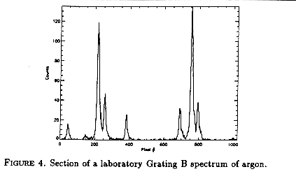 Preflight laboratory data confirm the realistic resolution to within
about 10%. Here jitter should be negligible, but the entrance pinhole
is comparatively large (25 µm). In these circumstances we expect
a resolution of about
Preflight laboratory data confirm the realistic resolution to within
about 10%. Here jitter should be negligible, but the entrance pinhole
is comparatively large (25 µm). In these circumstances we expect
a resolution of about ![]() /5500. In
Figure 4 we show a small section of a
laboratory spectrum of argon emission lines near 544 Å (Grating
B). The two bright features in this figure are separated by 4.26 k,
and show FWHM values of almost precisely
/5500. In
Figure 4 we show a small section of a
laboratory spectrum of argon emission lines near 544 Å (Grating
B). The two bright features in this figure are separated by 4.26 k,
and show FWHM values of almost precisely
![]() /5000.
/5000.
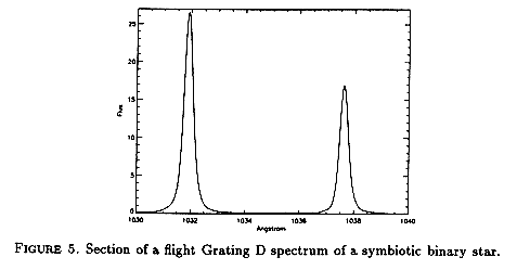 In Figure 5 we show a
small section of the spectrum of a symbiotic binary star near the
far-ultraviolet O VI lines (Grating D) collected during the ORFEUS-SPAS
I mission. The FWHM of these features is
In Figure 5 we show a
small section of the spectrum of a symbiotic binary star near the
far-ultraviolet O VI lines (Grating D) collected during the ORFEUS-SPAS
I mission. The FWHM of these features is
![]() /3000. Interstellar
absorption lines in continuous spectra show this characteristic width,
indicating that it is an instrumental limit, not an astrophysical
effect. Spacecraft jitter, for which no corrections were applied, would
limit the resolution at about
/3000. Interstellar
absorption lines in continuous spectra show this characteristic width,
indicating that it is an instrumental limit, not an astrophysical
effect. Spacecraft jitter, for which no corrections were applied, would
limit the resolution at about
![]() /5400.
The most natural explanation for
the A
/5400.
The most natural explanation for
the A
![]() /3000
is a defocus somewhere in the system as discussed above.
/3000
is a defocus somewhere in the system as discussed above.
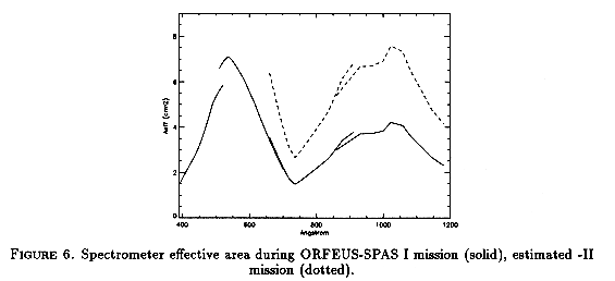 The in-flight effective area can be estimated from observations of the
well studied hot DA white dwarf G191-B2B (Vennes & Fontaine 1992). In
Figure 6 we show the in-flight effective area (solid line); this is
somewhat below preflight estimates based on "theoretical" expectations
for individual components, but not grossly so. The effective area was
about 10% higher upon initial instrument turn-on, but quickly declined
to the value shown here, then stabilized. This decline is presumably
associated with an initial outgassing of contaminants, which then
condensed on the optics and/or detector.
The in-flight effective area can be estimated from observations of the
well studied hot DA white dwarf G191-B2B (Vennes & Fontaine 1992). In
Figure 6 we show the in-flight effective area (solid line); this is
somewhat below preflight estimates based on "theoretical" expectations
for individual components, but not grossly so. The effective area was
about 10% higher upon initial instrument turn-on, but quickly declined
to the value shown here, then stabilized. This decline is presumably
associated with an initial outgassing of contaminants, which then
condensed on the optics and/or detector.
For the next mission, SiC
coatings on Gratings C and D should improve the effective area, as
shown by the dashed line in Figure 6. The 10% on-orbit loss may have
been recovered by postflight cleaning and recoating of the optics;
however, it could easily recur soon after deployment. At the time of
writing, the preflight calibration for the next mission has not been
carried out.
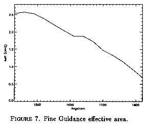 The effective area of the fine guidance system, again
estimated from ORFEUS-SPAS 1 observations of G191-B2B, is shown in
Figure 7. The barium fluoride entrance window of the sealed tube
reduces the effective area of this system to negligible values below
about 1400 Å.
The effective area of the fine guidance system, again
estimated from ORFEUS-SPAS 1 observations of G191-B2B, is shown in
Figure 7. The barium fluoride entrance window of the sealed tube
reduces the effective area of this system to negligible values below
about 1400 Å.
We acknowledge the support of NASA grant NAG5-696. The ORFEUS program is supported by DARA grant WE 3 50 OB 8501 3.
REFERENCES
GREWING, M. ET AL. 1991, The ORFEUS Mission, in Extreme Ultraviolet Astronomy, ed. R. F. Malina & S. Bowyer, New York: Pergamon, 437
HARADA, T. & KITA, T. 1980, Appl. Opt., 19, 3987
HARADA, T., KITA, T., HURWITZ, M., & BOWYER, S. 1991, International Conference on the Application and Theory of Periodic Structures, Proc. SPIE, 1545, 2
HURWITZ, M. & BOWYER, S. 1986, A High Resolution Spectrometer for EUV/FUV Wavelengths, Proc. SPIE, 627, 375
HURWITZ, M. & BOWYER, S. 1991, The Berkeley EUV Spectrometer for the ORFEUS Mission, in Extreme Ultraviolet Astronomy, ed. R. F. Malina & S. Bowyer, New York: Pergamon, 442
JENKINS, E. B., JOSEPH, C. L., LONG, D., ZUCCHINO, P. M. CARRUTHERS, G. R. BOTTEMA, M. & DELAMERE, W. A. 1988, Proc. SPIE, 932, 213
SIEGMUND, 0. H. W., LAMPTON, M., RAFFANTI, R., & HERRICK, W. 1991, High Resolution Delay Line Readouts for Microchannel Plates, Nuclear Instr. and Methods in Phys. Res., 310, 311
VENNES, S. & FONTAINE, G. 1992, An Interpretation of the Spectral Properties of Hot Hydrogen-Rich White Dwarfs with Stratified H/He Model Atmospheres, ApJ, 401, 288
|
|
|