


Raw IUE images suffer from geometric distortion introduced by the SEC vidicon
cameras. The electrostatically-focused image section of the camera produces a
pincushion distortion, while the magnetically-focused readout section produces
an S-distortion. An important part of the processing for each image is
compensation for these geometric distortions. Although the reduction of
spectral images under the current software no longer includes the explicit
generation of a geometrically corrected image (except as a step in the
creation of dispersion constants from wavelength calibration images and
intensity transfer functions (ITFs) from flat-field images - see
Figure
1-1,
and Sections
5 and 6
), implicit compensation for the geometric distortion of
the raw image is still required. To do this, positions of fiducial marks
(reseaux) are used, as they have been in the past, to map the distortion
across the image (see, for example, Thompson et al., 1980). In
Section
4.2
details regarding the measurement and modeling of reseau motion are
discussed, and in Sections
4.3 and
4.4 the methods used to parameterize
the geometric distortion and compensate for it in production processing
are presented.
The faceplate of each camera is etched with a square-grid pattern of 169
reseau marks arranged in 13 rows and 13 columns. The reseaux appear on images
as occulted areas approximately 2-3 pixels wide spaced approximately 55 pixels
apart (56-pixel separation for SWP, 55 pixels for LWP and LWR). According to
the design specifications of the scientific instrument (GSFC System Design
Report for the IUE, 1976), the placement of the reseau marks in a true square
grid is accurate to within ± 0.005 mm,
which corresponds to ± 0.14 pixels.
Once the positions of the reseau marks are measured on raw images
(approximately 129 of the 169 marks fall within the camera target area), the
departure of the observed positions from their true locations is used to
characterize the geometric distortion of the camera system.
Because reseau marks are in general poorly visible on all data images except
those with a substantial background level, information on reseau positions
used to model the geometric distortion for production processing has
standardly been obtained from measurements on flood-lamp exposures. Perry and
Turnrose (1977) provide a detailed description of the two-dimensional
cross-correlation search methods used to locate the
position of individual reseau
marks on such exposures. Improvements to software and procedures have been
subsequently made which affect various aspects of the reseau measurement
process and have been documented in Turnrose and Harvel (1982) and Turnrose,
Thompson and Gass (1984). These improvements made it possible to measure
reseaux on low dispersion (and to a certain extent high dispersion) wavelength
calibration (WAVECAL) images and basically include improved starting search
positions, smaller search areas, and the ability to "fill in" (using linear
interpolation) reseau positions which are not measurable due to superimposed
Pt-Ne emission lines. As a result, flat-field images are no longer used for
monitoring reseau motion and WAVECAL images are geometrically corrected using
reseau positions measured on the low dispersion WAVECAL images.
The above improvements also made it possible to expand the analysis of reseau
motion to include reseaux measured on low dispersion spectral images when the
background level is above approximately 40 DN. These new studies may
ultimately change the methods for compensating for geometric distortion used
in production processing (see Section
4.2.2.3.2).
Various studies of reseau motion as a function of time, temperature and image
intensity have been made over the last several years. One of the first
studies was that by Oliver et al. (1979),
which showed that shifts in reseau
positions on flat-field images could be correlated with both image intensity
and camera temperature. Later studies were primarily intended to determine
methods for compensating for this reseau motion in the production processing
of IUE images. For this reason studies were made of 60 percent ultraviolet
floodlamp (UVFLOOD) images (Thompson, Turnrose and Bohlin, 1982a), tungsten
floodlamp (TFLOOD) images and ITF UVFLOOD images (Thompson 1983a, 1984b) and
most recently, low dispersion spectral images (Thompson 1984c).
Although production processing currently uses only the results described in
Thompson, Turnrose and Bohlin (1982a) (see Section
4.3.1) the following
sections will describe the latest conclusions regarding the modeling of reseau
motion as a function of time, temperature, and image intensity.
Several problems exist in determining whether reseau motion is correlated with
time (i.e., date of observation), the most important of which is that there
does not exist a suitable set of images which (a) were obtained under similar
conditions of camera temperature and exposure level and (b) cover the entire
time period from launch to present. The first study of time dependence was by
Thompson, Turnrose and Bohlin (1982a) in which 60 percent UVFLOOD images
acquired over the first two years of IUE operation were examined for both
temperature and time dependence. Since the 60 percent UVFLOODs are all
exposed to the same intensity level, shifts due to beam-pulling effects (see
Section
4.2.2.3)
were minimized. A result of this study was that no evidence
for secular variation was found.
The question of time dependence was studied again by Thompson (1983a) using
TFLOOD images (~50 images each for LWR and SWP, ~25 images for LWP) and an
extended set of 60 percent UVFLOOD images. In this study a correlation with
time was discovered for the LWR UVFLOOD images. It was decided, however, that
the apparent correlation was probably due to a beam-pulling effect resulting
from a variation in the LWR UVFLOOD lamp itself, since the correlation was not
seen with the TFLOOD images.
The TFLOOD images, which cover the period from 1980 to present, represent the
largest consistent set of images available for monitoring reseau motion as a
function of time. No significant correlation with time has been seen for
these images. Any variation in reseau positions with time must be
significantly less important than the correlations found with temperature and
image intensity described below.
As discussed in detail in Thompson, Turnrose and Bohlin (1982a), the measured
positions of reseau marks on 60 percent UVFLOOD images change from image to
image due to a thermal sensitivity of the camera readout electronics (Oliver
et al., 1979).
These shifts, which are non-uniform across the image, range up
to a maximum of about 1.5 pixels at the edge of the SWP tube for a change in
THDA of 9C, have been correlated with camera head amplifier temperature
(THDA) for the LWR and SWP cameras. Linear regressions for the reseau
positions versus THDA have been established separately in the line and sample
directions for both the SWP and the LWR cameras. When all reseaux within the
target ring are considered, the average 1 sigma root-mean-square (rms) scatter
in position can be reduced from 0.29 to 0.19 pixels in SWP and from 0.24 to
0.21 pixels in LWR by applying temperature-dependent corrections to the
UVFLOOD reseau positions. Further information in tabular and graphical form
may be found in
Section
4.3.
The temperature correlations found with the 60 percent UVFLOOD images were
verified in a later analysis which included studies of both TFLOOD and UVFLOOD
reseau motion (Thompson 1983a). This study showed that an increase in THDA
resulted in a contraction of the overall reseau grid for both the LWR and SWP
cameras with the largest motion occurring in the SWP camera. A subsequent
study (Thompson 1984b) showed that LWP TFLOOD reseaux exhibited a slight
temperature dependence similar to that of the LWR reseaux.
The study of Oliver et al. (1979) showed
that reseau position shifts as large
as 1.5 pixels can be induced by "beam pulling effects". As explained in that
reference, the read beam is influenced by the charge distribution on the
target, so that for relatively highly exposed areas the apparent position of a
given pixel in the resulting image is shifted slightly in the general
direction of the top of the image. Their study concluded that (a) beam
pulling effects are largely confined to the immediate vicinity (i.e., within a
few pixels) of a feature and (b) for weak features extending over relatively
large areas, a much smaller long-range effect can be detected over distances
on the order of 100 pixels.
The localized nature of the strongest beam-pulling effects has made
compensation difficult, if not impossible. Partly for this reason, most of
the reseau motion studies which followed that of Oliver et al.
intentionally
used sets of images in which neither short-range nor long-range beam pulling
effects contributed to the relative reseau motion. Therefore, the studies
based on TFLOOD and 60 percent UVFLOOD reseau positions, although useful for
evaluating temperature and time correlations, do not provide any information
on beam-pulling effects. Because the geometric correction in production
processing is based on results from the study of 60 percent UVFLOOD images
(see
Section
4.3),
some systematic errors are probably being introduced. Section
6.5
contains a discussion of the magnitude of such systematic effects
as they pertain to wavelength assignments.
An attempt to parameterize the reseau motion due to beam-pulling effects was
recently made as a result of a study of ways to improve the geometric
correction of ITF images. Correlations of reseau motion as a function of mean
DN level and temperature were determined for a series of ITF UVFLOOD images
taken at different exposure levels. After application of the deduced DN and
temperature correlations the resulting residual scatter in reseau positions
among three separate series of ITF images was always less than 0.08 pixels,
which is less than that found from any other study (see Thompson 1983a).
As a result of the above findings (and because of the limited number of
available ITF UVFLOOD images), an on-going study of reseau motion in low
dispersion spectral images was initiated. As reported by Thompson (1984c),
results show that for each camera, a correction based on a mean DN level is
more significant in reducing the residual scatter than a correction for
temperature. The continuing work in this study will most likely result in an
improvement to current production processing procedures in the near future.
As actually utilized in production processing, the reseau positions are
expressed in terms of displacements which are the differences between the
reseau positions as found on raw images and the actual 13 x 13 grid of reseau
marks located between the UV converter and the SEC vidicon camera.
Displacements for reseaux lying outside of the camera target area are
calculated by linear extrapolation of the measured displacements. As
explained in Section
4.4
it is these displacement files (after the application
of any parameterized corrections as described below) that are used by the
IUESIPS application programs to compensate for the geometric distortion in IUE
images.
Prior to mid-July 1980 the displacement files used in production processing
were based on smoothed reseau positions obtained from TFLOOD exposures
acquired approximately every two weeks. Chebyshev polynomials were used to
smooth the rows and columns of the reseau grid prior to the generation of the
displacement files. After the above date, the displacement files were created
from averages of reseau positions measured on 60 percent UVFLOOD exposures,
without applying the polynomial smoothing mentioned above. The advantages to
this method are described in Thompson et al. (1980). A correction for
thermal shifts for the SWP camera was finally implemented in March 1981 for
low dispersion images and in May 1981 for high dispersion images as explained
in Thompson, Turnrose and Bohlin (1982a). The following sections describe in
more detail the displacement files currently used for each camera in
production processing.
Because the overall improvement for LWR reseau positions after temperature
correction was so marginal (as explained in Section
4.2.2.2), and because
there are no large local deviations, the THDA correction has not been applied
in LWR production processing. The lack of improvement is shown graphically in
Figure
4-1
which shows, for each reseau, the 1 sigma scatter before and after
correction in the directions along and perpendicular to the high dispersion
orders.
 Figure 4-1a.
a. Scatter in the Two Orthogonal Directions (Along and
Perpendicular to High Dispersion Orders) for the Reseau
Locations as Observed on 15 LWR Flat-Field-Images. The
Length of the Bars Represents >1s. (Same as Figure 5a of
Thompson, Turnrose, and Bohlin 1982a).
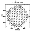 Figure 4-1b.
b. As Above, but After Applying Temperature Corrections. (Same
as Figure 5b of Thompson, Turnrose, and Bohlin 1982a).
The LWR displacement file used in production processing was generated using
the mean reseau positions of 15 60 percent UVFLOOD images (Thompson, Turnrose
and Bohlin 1982a). These mean displacements (i.e., mean found minus actual
positions) are shown in Table
4-1. The actual sample positions are the first
row of integers at the top of the tables, while the actual line numbers are
the first column. The displacements at each actual reseau position in
Table
4-1
are listed in sample (upper entry) and line (lower entry) pairs. The mean
displacements are illustrated graphically in Figure
4-2. In this display, the
actual positions of the 169 reseaux are marked by diamonds; the displacements,
magnified for visual clarity by a factor of two, are indicated by the
vectors. The amount of distortion is therefore exaggerated for display,
although the directions and relative proportions of the displacements are
correct.
Because the overall improvement for SWP reseau positions after temperature
correction is significant and because even larger local improvements are
realized, the THDA correction is applied in SWP production processing, based
on the THDA at the time the image is read, as extracted from the camera
snapshot portion of the image science header. If the THDA at the time of read
cannot be extracted from an image header, the processing defaults to the mean
reseau displacements (given in Table
4-2 and shown graphically in Figure
4-3
as for LWR) unless a specific THDA value is manually specified by the operator
when the image is processed.
The temperature-corrected SWP reseau displacements are equal to a value R(s)
samples and R(l) in lines determined from
R(s) = R1(s) + R2(s) × THDA
R(l) = R1(l) + R2(l) × THDA
where the R1 and R2 values are given in Tables
4-3 and
4-4 in the position
corresponding to the same line or sample displacement in Table
4-2. The
improvement due to temperature correction is seen in Figure
4-4 which displays
the 1s scatter before and after correction in the same form as shown for LWR
in Figure
4-1.
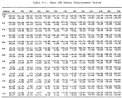 Table 4-1:
Mean LWR Reseau Displacement Values
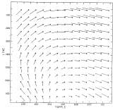 Figure 4-2:
Displacements of Mean Reseaux from Correct Grid LWR (Magnified by 2).
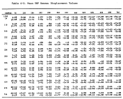 Table 4-2:
Mean SWP Reseau Displacement Values
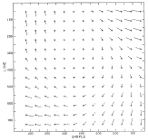 Figure 4-3:
Displacements of Mean Reseaux from Correct Grid SWP (Magnified by 2).
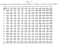 Table 4-3:
R1 Constants for SWP Displacement Correction (Table 4 of Thompson, Turnrose,
and Bohlin (1982a)
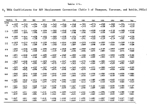 Table 4-4:
R2 THDA Coefficiencts for SWP Displacement Correction (Table 5
of Thompson, Turnrose, and Bohlin 1982a)
 Figure 4-4:
a. Scatter in the Two Orthogonal Directions (Along and
Perpendicular to High Dispersion Orders) for the Reseau
Locations as Observed on 18 SWP Flat-Field Images. The length
of the Bars Represents > 1 sigma. (Same as Figure 4a of
Thompson, Turnrose, and Bohlin 1982a).
b. As above, but After Applying Temperature Corrections. (Same
as Figure 4b of Thompson, Turnrose, and Bohlin 1982a).
The current LWP displacement file was generated from an average of three 60
percent UVFLOOD images obtained in 1980. As for the other cameras, these mean
displacements are shown in Table
4-5 and graphically in Figure
4-5. The
limited number of available LWP UVFLOOD images prevented more images from
being included in the analysis and prevented any correlations with time, THDA,
or DN from being determined.
The SWR is not an operational camera at this time.
Information identifying the parameters pertinent to the geometric compensation
applied to any particular image is documented by entries made in the
processing history portion of the image label, in a format described in
Section
9.
This information includes an identifier for the reseau set used,
the THDA value used for temperature correction, if appropriate, and other
relevant data.
Based upon the reseau displacements appropriate to each image and computed as
described in the preceding sections, the geometric distortion in that image is
compensated for during processing by a mapping function which calculates
interpolated displacement values at any point within the image. This mapping
function establishes the correspondence between points in the raw (distorted)
image and points in a geometrically correct (undistorted) image. If we
designate the function which transforms sample and line coordinates (s,l) in
the raw image to sample and line coordinates (x,y) in the geometrically
correct image as
(x,y) = G(s,l)
(following Lindler, 1982a) then the inverse function G-1 transforms
geometrically correct coordinates to raw coordinates:
(s,l) = G-1(x,y)
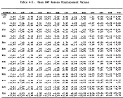 Table 4-5:
Mean LWP Reseau Displacement Values
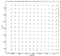 Figure 4-5:
Displacements of Mean Reseaux from Correct Grid LWP (Magnified by 2).
Because the function G-1 is derivable directly from the reseau displacement
file by interpolation, it is used throughout the new software system to
actually perform the geometric mapping. In certain situations, however, the
function G is a conceptually convenient tool to use in explaining geometric
relationships and will be used in several discussions in succeeding sections.
Following Lindler (1982a), let dij represent the displacement vector of the
reseau marks in row i, column j of the reseau grid. To find the position
(s,l) in raw space corresponding to the arbitrary position (x,y) in
geometrically correct space, one needs to calculate the displacement vector
d = (dx,dy) for the point (x,y).
This is done via a bilinear interpolation of
the reseau displacements, using the following steps.
- Determine the four reseau positions between which the
point (x,y) lies. That is, if xj is the sample
coordinate for reseau column j and yi is the line
coordinate for reseau row i in geometrically correct
space, then determine i and j such that
x
j < x < x
j+1
y
i < y < y
i+1
- Compute the fractional distances u and v:
u = (x - xj) ÷ (xj+1 - xj)
v= (y - yi) ÷ (yi+1 - yi)
- Compute the displacement d by interpolation:
d = (dx,dy) = (1-u)(1-v)di,j + (1-u)vdi+1,j + u(1-v)di,j+1 + uvdi+1,j+1
Having calculated the appropriate displacement vector d, one can then
compute the sample and line coordinates in raw space:
(s,l) = (x+dx,y+dy) = G-1(x,y)
Under the old IUE software, the function G-1 was used to perform the mapping
needed for doing the explicit geometric correction of images. Although this
explicit correction is now done only for wavelength calibration and certain
flat-field images as mentioned in Section
4.1,
the same function G-1 is still
used in the new software to refer positions associated with geometrically
correct space back to the corresponding raw-image positions.
4.4.2 RAW-TO-GEOM MAPPING FUNCTION G
The inverse of the function G-1 is the function
(G-1)-1 = G. Although, as
explained earlier, the function G is not used algorithmically in the actual
software, it is conceptually useful in describing the relationship between
raw-image space and the geometrically corrected intensity transfer function in
the context of the photometric correction process (see Section
5).
In general, the accuracy of the compensation for geometric distortion is not
directly measured. However, errors in the distortion compensation can be seen
by their effect on the wavelength assignment accuracy (Section
6.5), the
photometric correction (Section
5), the registration procedure described in Section
6.3.2,
and the accuracy of the gross and background flux extraction in
high dispersion (Section
7.1).
The errors involved can derive from both (a) errors in the found reseau
positions used and (b) small-scale distortions which are not corrected by
simple linear interpolation between the reseau positions. The latter error is
seen as "wiggles" in the spectral orders and has been described by several
authors; see Panek (1982b), de Boer and Meade (1981), Thompson (1982), and
Cassatella, Barbero and Benvenuti (1983).


 Figure 4-1a.
a. Scatter in the Two Orthogonal Directions (Along and
Perpendicular to High Dispersion Orders) for the Reseau
Locations as Observed on 15 LWR Flat-Field-Images. The
Length of the Bars Represents >1s. (Same as Figure 5a of
Thompson, Turnrose, and Bohlin 1982a).
 Figure 4-1b.
b. As Above, but After Applying Temperature Corrections. (Same
as Figure 5b of Thompson, Turnrose, and Bohlin 1982a).


