


The concept of the IUE header label has been discussed in several sections of
this document (see, for example, Sections
2.1 and
8.2.1). The label generated
at the time of image acquisition is passed through to the processing system
along with the image data and is appended in sequential fashion to record
significant processing parameters.
The discussion of Section
8.2.1
focussed on the physical and logical record
format of image labels on tape, without regard to their actual contents.
Similarly, in other sections of this document, the kinds of data added to the
processing history portion of the label were discussed generally, without
regard to specific formats within the label records. In this section, the
contents of image labels are presented and explained so that users may more
usefully interpret the documentary information in the labels.
Throughout this section, the illustrative displays of labels and portions
thereof are in the form in which they would appear on the labelprint listings
described in Section
8.1.4. In particular, the character decoding is EBCDIC,
so that binary-format label entries are not decoded properly. Since the
binary portions of the label are, with the exception of the "camera snapshot"
entries pertaining to camera temperature data, not used by the processing
system, little documentation of the binary data is presented herein. Users
are referred to Thomason and Cheng (1978) for the original format
specifications for the science header.
The appearance of a typical raw-image label obtained from a labelprint listing
of a GO tape is illustrated in Figure
9-1. The basic 100-logical-record
format is readily apparent, as is the short image processing history portion
appended as the file was written to tape. As will be apparent in Section
9.3 ,
this image processing history expands significantly for subsequently derived
files (processed data). Table
9-1 contains an explanatory key to the most
significant individual fields in the raw-image label.
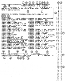 Figure 9-1a:
Labelprint Listing for Raw Image File (RI), Part 1.
Figure 9-1a:
Labelprint Listing for Raw Image File (RI), Part 1.
 Figure 9-1b:
Labelprint Listing for Raw Image File (RI), Part 2.
Figure 9-1b:
Labelprint Listing for Raw Image File (RI), Part 2.
Table 9-1. Key to Figure 9-1
| Field | Contents |
|---|
|
1 | Starting line (record no.) of data file | (bytes 25 - 28) |
|
2 | Starting sample (byte no.) of data file
| (bytes 29 - 32) |
|
3 | Number of lines (records) in data file
| (bytes 33 - 36) |
|
4 | Number of samples (bytes per record) in data
| (bytes 37 - 40) |
file. Fields 1-4 collectively comprise the
"size parameters" for the data file.
|
5 | Camera scan step size (1-4)
| (byte 44) |
|
6 | EDS file no. (1 or 2)
| (byte 46) |
|
7 | Station flag (0 = HANDOVER, 1 = GSFC,
2 = VILSPA)
| (byte 49) |
|
8 | Camera no. (1 = LWP, 2 = LWR, 3 = SWP,
4 = SWR, 8 = FES1, 9 = FES2)
| (byte 50) |
|
9 | Dispersion flag (0 = high, 1 = low)
| (byte 51) |
|
10 | Image sequence no. (1-99999)
| (bytes 52 - 56) |
|
11 | Running number of label line
| (bytes 67 - 69) |
|
12 | Continuation character (C = more lines
follow, L = this is last line of label)
| (byte 72) |
|
13 | SOC tape (raw image archive tape) no. |
|
14 | File no. of raw image on SOC tape |
|
15 | Total time camera was turned on (seconds),
taken from FIN entry (see field no. 24).
Sum of all exposures if more than one is taken.
This is not a true exposure time for trailed
spectra. |
|
16 | Guest Observer comments section, entered by
telescope operator |
|
17 | Event "round-robin" section describing time-
tagged sequence of procedures. Entries all begin
with GMT time in hhmmss format. Oldest entries
appear below the double blank lines. Note:
SWLA = short wavelength large aperture, LWSA =
long wavelength small aperture, etc. |
|
18 | Year of read |
|
19 | GMT day of read |
|
20 | Approximate time of read in hours, minutes, and
seconds GMT |
|
21 | Exposure start tag. GMT time given is near start of
exposure. Format is:
EXPOBC cam. no. Tmintsec gain lamps
where
Tmintsec
is the commanded duration of "camera-on"
time (seconds are rounded). Actual duration may be modified
by a subsequent MODTIME command. |
|
22 | Exposure end tag. GMT time given is usually near end of
exposure but can be much later. Format is:
FIN cam. no. T t S sec voltage U uvc voltage,
where t is the total cumulative duration of "camera-on" time achieved
in seconds (truncated) since last read of camera in question. Due to
truncation, duration may not agree with that in EXPOBC tag. |
|
23 | Exposure start tag, in this case for the second aperture. |
|
24 | Exposure end tag, in this case following exposure in second
aperture and showing truncated cumulative time for both apertures.
Time in seconds here is passed to field no. 15. |
|
25 | Readprep tag. GMT time given is near start of image read
process. Format is:
READPREP cam. no. IMAGE image sequence no. |
|
26 | Program ID |
|
27 | Episode no. (1, 2, 3,. . . etc.) |
|
28 | Observer sign on name |
|
29 | Target list sequence no. |
|
30 | Catalog source (H, B, D,. . . etc.) |
|
31 | Object name |
|
32 | Object classification |
|
33 | Right ascension of object (hhmmsst where t is tenths of
seconds of time) |
|
34 | Declination of object (± ddmmss of arc) |
|
35 | Spectral type |
|
36 | Luminosity class (1-9) |
|
37 | V magnitude or flux |
|
38 | Color excess E(B-V) or color B-V |
|
39 | Information from Preplanned Observation Tape (POT) |
|
40 | Binary section of label |
|
41 | Binary section of label |
|
42 | Orbital elements, periodically updated, for epoch
specified by fields 43 and 44 |
|
43 | Julian Date |
|
44 | Seconds since midnight of JD in field 43 |
|
45 | a, semimajor axis (km) |
|
46 | e, eccentricity |
|
47 | i, inclination (deg)
|
|
48 |
 , longitude of ascending node (deg)
|
|
49 |
 , argument of pericenter (deg)
|
|
50 | M, mean anomaly (deg)
|
|
51 | Spacecraft attitude commands sent to spacecraft (most
recent set of four) |
|
52 | Day:hour:min:sec at which new attitude commanded |
|
53 | Right ascension commanded (hhmmsst where t is tenths of
seconds of time) |
|
54 | Declination commanded (± ddmmss of arc) |
|
55 | Spacecraft roll angle (dddmmss of arc) |
|
56 | Binary section of label |
|
57 | Image processing history section of label |
|
58 | File type identifier and image processing scheme name (see Figure
9-2 and Table
9-2) |
|
59 | Identifier for image processing program name and time (GMT)
of image processing scheme initiation |
Note that lines 3-9 are entered by the telescope operator at the console and
may occasionally contain errors. Lines 36-37, normally input from the POT,
may be modified by the telescope operator and hence are also subject to
errors. The automatic entries on the other lines are more accurate but can be
affected, for instance, by ground computer problems (see also Section
9.5.1).
As is apparent from Figure
9-1,
the binary-format portion of the raw-image
label in logical records 38-82 and 86-100 is not usefully decoded when
interpreted in EBCDIC characters. The camera snapshot entries in logical
records 86-100 are scanned by the processing system as described in Turnrose,
Harvel, and Mallama (1982) in order to extract information on the camera head-
amplifier temperature (THDA) which is in turn used to correct geometric
distortion and dispersion-constant files for thermal effects (Sections
4 and
6).
Users are referred to Turnrose, Harvel, and Mallama (1982) for details.
As images proceed through the various reduction steps performed by IUESIPS,
records are appended to the raw image label to document the parameters
describing the processing. This is a cumulative process so that the label of
the end product (extracted spectral data) contains all entries added at
earlier stages. In the following sections, examples of only the final low and
high dispersion merged extracted spectra (MELO, MEHI) labels are discussed.
A labelprint listing of an SWP merged low dispersion extracted spectral (MELO)
file is reproduced in Figure
9-2. Note that, as pointed out in Section
8.1.4,
logical records 6-100 are suppressed in such listings; none of the image-
processing history records are suppressed, however. Table
9-2 contains an
explanatory key to the fields marked in Figure
9-2.
Information identifying lines in the raw image affected by microphonic
noise (see Section
3.1 )
is currently provided for LWR images only; an example
is given in Section
9.3.2.
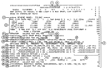 Figure 9-2:
Labelprint Listing for Merged Low Dispersion Extracted Spectral File (MELO)
Figure 9-2:
Labelprint Listing for Merged Low Dispersion Extracted Spectral File (MELO)
The information pertaining to the reseau displacements and thermal corrections
thereof is documented in two separate lines of the label (fields 18-20). In
this example, the label data state the following: the mean reseau
displacements used were calculated from images acquired between GMT day 085 of
1978 and day 334 of 1979 (note that the entries in the label are not in
decimal-year notation), 18 flat-field images from this time period were used
to calculate the mean, and the average 1
 scatter values among these images in
the sample and line directions are 0.134 and 0.138 pixels, respectively.
scatter values among these images in
the sample and line directions are 0.134 and 0.138 pixels, respectively.
The camera head amplifier temperature (THDA) at the time of image read
obtained from the camera snapshot data (see Turnrose, Harvel and Mallama,
1982) is documented in field 19. This temperature is used as described in
Section
4
to calculate thermally-corrected displacements, as appropriate.
Should a specific THDA value ever be manually entered into the processing
scheme to override camera snapshot data, the words "MANUAL OVERRIDE" would be
added to this label record. Furthermore, when mean reseau displacements
rather than temperature-corrected displacements are used, the message "MEAN
RESEAU USED" would appear in field 20 (see Figure
9-3 for such a message).
Such a situation will currently always occur for LWR or LWP data and will also
occur for SWP data for which a valid THDA value is not available from either
the camera snapshots or manual input.
The information pertaining to the dispersion relations and thermal/temporal
corrections is documented in a number of lines of the label (fields 21-26).
In this example, the label data indicate that the mean dispersion relations
used were calculated from images acquired between GMT day 001 of 1980 and day
222 of 1982 (again this is not a decimal-year notation); that 44 wavelength
calibration images from this time period were used to calculate the mean; and
that the average 1s residual scatter values after correction for time and
temperature effects in the sample and line directions are 0.287 and 0.252
pixels, respectively.
The camera head amplifier temperature (THDA) at the time of the end of the
exposure, as obtained from the camera snapshot data, is documented in field 22
and used as described in Section
6 to calculate the thermal shift of the
dispersion relation. If the THDA at the end of exposure is not available from
the camera snapshots, the THDA at the time of image read is used and the words
"AT TIME OF READ" would be added to the label record. In the event that a
specific THDA value is manually entered into the processing scheme to override
camera snapshot data, the words "MANUAL OVERRIDE" would be added to this label
record. If the THDA is not available from the header label or manual input
but the time of read is determined (either specified manually or extracted
from the label) then a correction for time only is applied and the message
"MEAN THDA" will appear in field 22 signifying a default to the mean THDA
value. If neither the THDA nor the time of read is available from either the
header label or manual input, the message "MEAN DC USED" is added to indicate
that the processing defaulted to mean dispersion constants. Note that even in
such an instance, the sigma values given in the label are still the average
residuals described above.
The information labeled "THERMAL SHIFTS" in field 23 documents the net
time/temperature shifts applied to the mean dispersion constants (see Section
6). The shifts labeled "REGISTRATION SHIFTS" in field 24 represent the
residual shifts needed after the "THERMAL SHIFTS" listed above are applied to
register the extraction slit with the order (see Section
6). For registration
shifts determined manually (i.e., by operator intervention) the word "MANUAL"
appears after the shift values; for registration shifts determined
automatically by the software system, the word "AUTO" appears instead, as in
this example.
The final dispersion constants (after all shifts have been applied) actually
used in the spectral extraction step are recorded in the B (line direction)
and A (sample direction) arrays in fields 25 -26.
A labelprint listing of an LWR merged high dispersion extracted spectral
(MEHI) file is reproduced in Figure
9-3, and an explanatory key is provided in
Table
9-3. The majority of the fields in the image-processing history are the
same as described for the low-dispersion case in Section
9.3.1, and so are not
described again here. Note that the label of course reflects processing by
the high dispersion programs SPECHI, SORTHI, and POSTHI instead of the low
dispersion programs SPECLO and POSTLO. Also, in this example, the presence of
microphonics is recorded (fields 1 and 2).
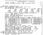 Figure 9-3:
Labelprint Listing for Merged High Dispersion Extracted Spectral File (MEHI)
Figure 9-3:
Labelprint Listing for Merged High Dispersion Extracted Spectral File (MEHI)
The fields which are unique to high dispersion processing are those relating
to the echelle ripple correction and to the velocity corrections made to
reduce the wavelengths to a heliocentric frame of reference. The ripple
correction parameters, applied as discussed in Section
6
, are given in fields
3 and 4.
The velocity components of the IUE satellite and the earth in a right-handed
equatorial coordinate system, calculated as described in Section
6
, are given
in fields 5 - 6. The resulting net radial velocity correction, whose
wavelength equivalent is added to the extracted wavelengths in order to obtain
the heliocentric wavelengths, is given in field 7; see Section
6
for
computational details.
The single-record label associated with the Tape Header file described in
Section
8.2.1.2
is illustrated in the labelprint listing of Figure
9-4. Note
that all information in the label is in EBCDIC format, and no size-parameter
field is present.
The label associated with a file of reseau positions is illustrated by
the labelprint listing of Figure
9-5
. The identifying information in bytes
41-72 of line 1 of the label is the same as that in the label of the image
from which the reseau positions were derived.
 Figure 9-4:
Labelprint Listing for Tape Header File
Figure 9-4:
Labelprint Listing for Tape Header File
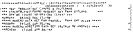 Figure 9-5:
Labelprint Listing of Reseau-Position File
Figure 9-5:
Labelprint Listing of Reseau-Position File
There are occasions when the information contained in lines 1-100 of the image
header label is either in error, unreadable or missing altogether. Although
unusual, these problems can affect the processing of spectral data by IUESIPS,
particularly since the implementation of the new software which relies more
heavily than the earlier software on the data stored in the image header
label. The cases in which these errors are known to occur are described
below.
- History Playback Images. When a problem occurs with
the archiving of IUE images during real-time operations,
the spectral data can generally be recovered from the
history tapes which record the spacecraft telemetry
stream. Unfortunately, since the science header is
generated by the ground system and is not contained in the
telemetry stream, the history tapes cannot be used to
recreate image header labels. Therefore when a history
playback request is made, the header label generated
contains only data input with the request. Such labels
will not contain any of the binary data, (including all of
the temperature information used as described in Sections
4 and
6),
will lack the event "round-robin" portion of the
label, and may lack the observer's comments and additional
data as well.
- Corrupted Labels. An error was discovered in an
IUESIPS utility program called ULFLBM which could corrupt
the binary-data portions of the header label. Apparently
the routine deleted from the label bytes which were not
recognized as EBCDIC characters. The error was not
discovered until June 13, 1983, so that images processed
before that date could be affected by this problem,
although the program was in fact rarely used. A more
detailed description of this problem is contained in
Turnrose, Thompson and Gass (1984).
- Incorrect Label Information. Occasionally the
information stored in the label is either misinterpreted
by the IUESIPS software (e.g., when the time in line 2 is
used as the exposure time for a multiple-exposure image)
or the label data are simply incorrect.
As explained below, procedures now exist for modifying
labels with incorrect data; however, such modification
usually requires that the error be discovered before the
image is processed and that the correct information be
known.
- Truncated Labels. During the period from April 25,
1978 to February 6, 1979, some high dispersion IUE images
were partially processed on an IBM 360 computer and, as a
result, the header labels of these files were truncated
(i.e., lines 11-35, 38-45, 47-82, and 84-85 were removed
from the label). See Turnrose and Harvel (1982) for
details.
The dependence of the new software on information extracted from the image
header label requires that IUESIPS have the ability to correct known label
errors. For this reason, software was written to allow the image processing
specialist to correct label entries pertaining to the camera number, image
sequence number, program ID, exposure time, right ascension, declination, and
date of observation. The applications program which allows the modification
of these label entries, LABFIX, was first used in December 1981. All other
label entries, such as the binary label data and the event status portion of
the label were left uncorrected, primarily because of the difficulty in
correcting these entries and in knowing the correct data to enter.
It was subsequently decided that a better policy would be to leave the
original header intact and deal with corrections in an alternative way. The
project therefore agreed that the IUESIPS software should eventually be
modified to search for an appendage to the header label which would contain
any corrections to data stored in lines 2 - 100. Line 1 would still be
allowed to be modified directly, because of the importance of entries in this
line as identifiers and keys used by numerous software systems. Because such
an alternative procedure would require changes to almost every major IUESIPS
applications program, an interim policy was agreed to in which although the
label entries mentioned above would continue to be corrected
in situ, the
original (uncorrected) entries would also be stored in an appendage to the
label. The applications program LABCOR which creates such an appendage was
first used in February 1983.
The documentation and correction of errors discovered in the image-processing
history portion of the IUE image header label is described in detail in
Turnrose and Harvel (1982) and Turnrose, Thompson and Gass (1984). A summary
of all changes to the image processing history portion of the label is
contained in Thompson (1984d).
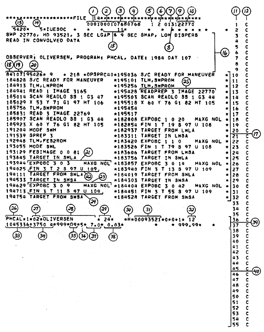 Figure 9-1a:
Labelprint Listing for Raw Image File (RI), Part 1.
Figure 9-1a:
Labelprint Listing for Raw Image File (RI), Part 1.
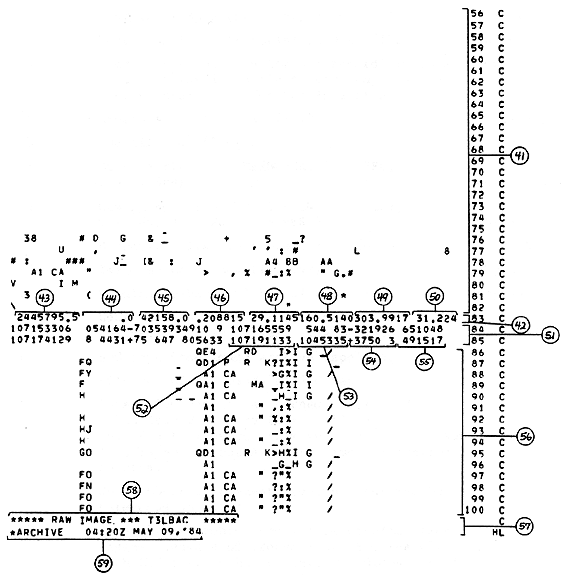 Figure 9-1b:
Labelprint Listing for Raw Image File (RI), Part 2.
Figure 9-1b:
Labelprint Listing for Raw Image File (RI), Part 2.
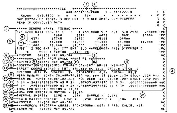 Figure 9-2:
Labelprint Listing for Merged Low Dispersion Extracted Spectral File (MELO)
Figure 9-2:
Labelprint Listing for Merged Low Dispersion Extracted Spectral File (MELO)
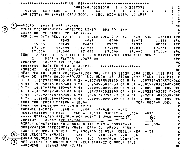 Figure 9-3:
Labelprint Listing for Merged High Dispersion Extracted Spectral File (MEHI)
Figure 9-3:
Labelprint Listing for Merged High Dispersion Extracted Spectral File (MEHI)
 Figure 9-4:
Labelprint Listing for Tape Header File
Figure 9-4:
Labelprint Listing for Tape Header File
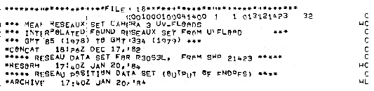 Figure 9-5:
Labelprint Listing of Reseau-Position File
Figure 9-5:
Labelprint Listing of Reseau-Position File