Each raw IUE image consists of a 768 by 768 array of 8-bit picture elements or "pixels". (Partial-read" images, which are not full 768 by 768 images, are discussed in Section 3.3.) Each vidicon scan line consists of 768 pixels or "samples"; 768 such scan lines compose the entire image. Line 1, sample 1 is at the upper left corner of the image; line 768, sample 768 is at the lower right corner of the image. Each raw pixel value lies in the range 0 to 255 (integers only). The units of raw pixel values are DN (or data numbers), which are proportional (up to the telemetry system limit of 255) to the integrated charge read out from the SEC vidicon target in the camera scanning process. Since the telemetry system saturates at 255, at that level the DN/charge proportionality breaks down.
Associated with each raw image is a set of 20 header, or label, records. Each record is 360 8-bit bytes long (a concatenation of five 72-byte logical records). This set of 20 label records is generated by the IUE Operations Control Center (OCC) software during image acquisition and contains various identifying parameters and scientific/engineering data pertinent to the image. The label associated with a given image is then expanded (up to a maximum of 42 records) to contain a log or history of the image processing operations in a manner which is illustrated in Section 9 , where a detailed description of the standard label-record formats will be found.
Raw IUE images must be corrected for the instrumental effects of the SEC vidicon camera system before quantitatively meaningful data can be extracted from them. The geometric distortion and photometric nonlinearities and nonuniformities introduced by the vidicon system are compensated for by the methods described in Sections 4 and 5. The layout of the spectral format in either dispersion mode is mathematically described by the methods discussed in section 6. Figures 2-1 through 2-15 illustrate schematically the spectral formats in both dispersion modes, for both apertures and all three operational cameras. These diagrams refer to raw image space. The square border defines the 768 by 768 array comprising the whole image, whereas the inscribed arcs define the area within which photometric correction is made (see Section 5) and from which spectral information is extracted. For high dispersion, the extracted odd and even echelle orders are shown in separate figures. Numbers and tick marks along the borders mark the wavelengths in angstroms (Å).
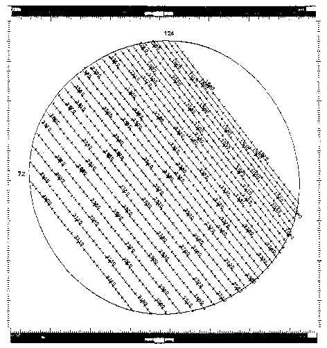 Figure 2-1.
Schematic Representation of the Echelle (High Dispersion)
Spectral Format in the Long Wavelength Prime (LWP) Camera,
Small Aperture (Even Orders From 124 to 72)
Figure 2-1.
Schematic Representation of the Echelle (High Dispersion)
Spectral Format in the Long Wavelength Prime (LWP) Camera,
Small Aperture (Even Orders From 124 to 72)
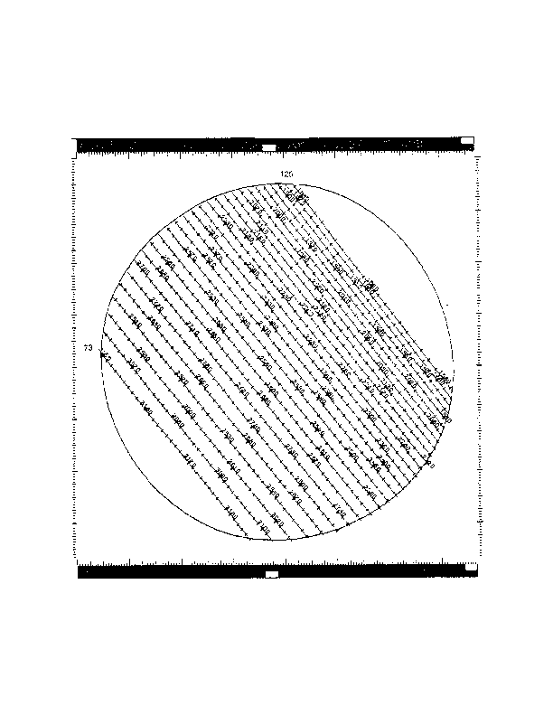 Figure 2-2.
Schematic Representation of the Echelle (High Dispersion)
Spectral Format in the LWP Camera, Small Aperture (Odd Orders
From 125 to 73)
Figure 2-2.
Schematic Representation of the Echelle (High Dispersion)
Spectral Format in the LWP Camera, Small Aperture (Odd Orders
From 125 to 73)
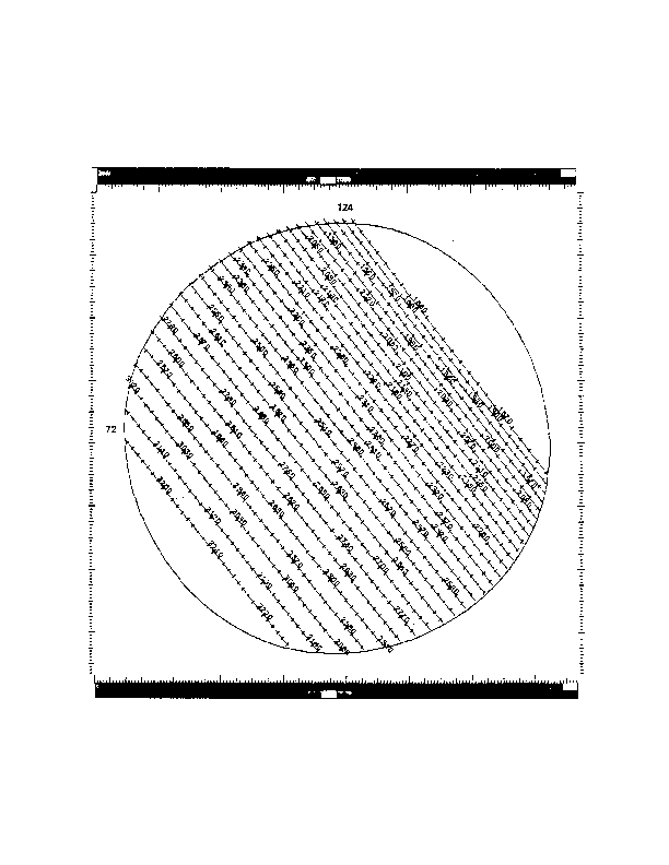 Figure 2-3.
Schematic Representation of the Echelle (High Dispersion)
Spectral Format in the LWP Camera, Large Aperture (Even
Orders From 124 to 72)
Figure 2-3.
Schematic Representation of the Echelle (High Dispersion)
Spectral Format in the LWP Camera, Large Aperture (Even
Orders From 124 to 72)
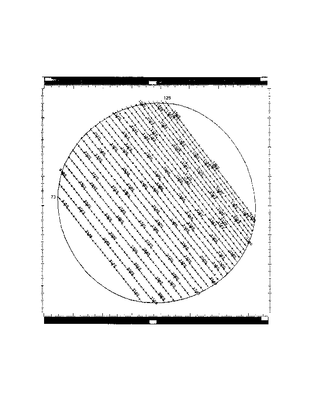 Figure 2-4.
Schematic Representation of the Echelle (High Dispersion)
Spectral Format in the LWP Camera, Large Aperture (Odd
Orders From 125 to 73)
Figure 2-4.
Schematic Representation of the Echelle (High Dispersion)
Spectral Format in the LWP Camera, Large Aperture (Odd
Orders From 125 to 73)
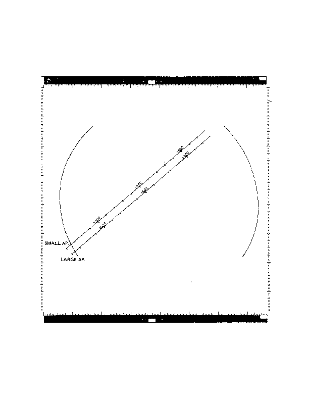 Figure 2-5.
Schematic Representation of the Low Dispersion Spectral Format
in the LWP Camera, Both Apertures
Figure 2-5.
Schematic Representation of the Low Dispersion Spectral Format
in the LWP Camera, Both Apertures
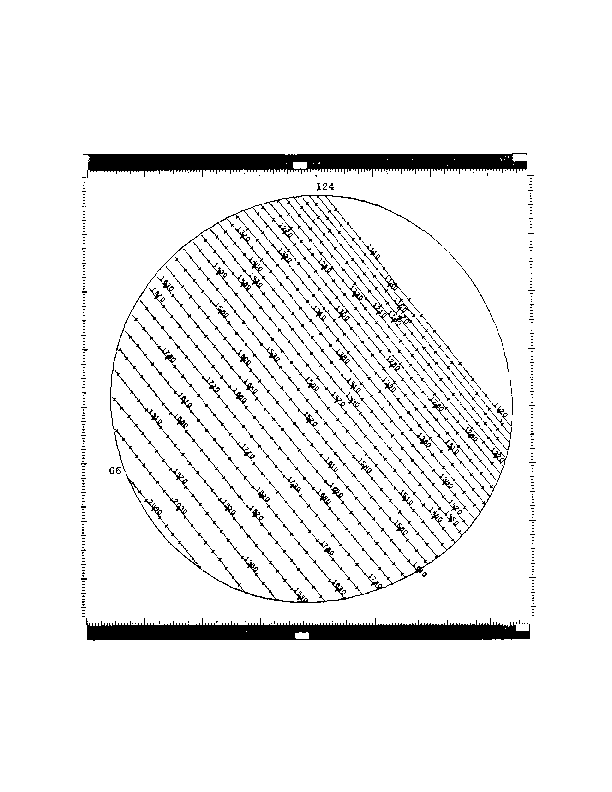 Figure 2-6.
Schematic Representation of the Echelle (High Dispersion)
Spectral Format in the Short Wavelength Prime (SWP) Camera,
Small Aperture (Even Orders From 124 to 66)
Figure 2-6.
Schematic Representation of the Echelle (High Dispersion)
Spectral Format in the Short Wavelength Prime (SWP) Camera,
Small Aperture (Even Orders From 124 to 66)
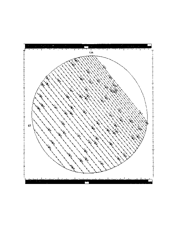 Figure 2-7.
Schematic Representation of the Echelle (High Dispersion)
Spectral Format in the SWP Camera, Small Aperture (Odd Orders
From 125 to 67)
Figure 2-7.
Schematic Representation of the Echelle (High Dispersion)
Spectral Format in the SWP Camera, Small Aperture (Odd Orders
From 125 to 67)
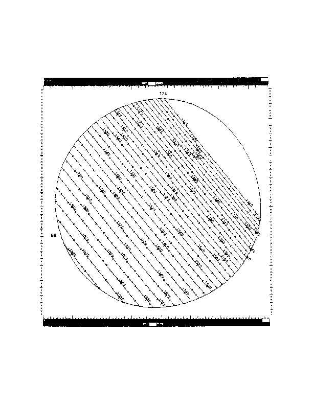 Figure 2-8.
Schematic Representation of the Echelle (High Dispersion)
Spectral Format in the SWP Camera, Large Aperture (Even Orders From 124 to 66)
Figure 2-8.
Schematic Representation of the Echelle (High Dispersion)
Spectral Format in the SWP Camera, Large Aperture (Even Orders From 124 to 66)
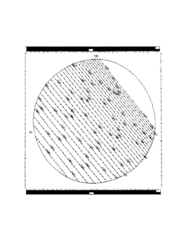 Figure 2-9.
Schematic Representation of the Echelle (High Dispersion)
Spectral Format in the SWP Camera, Large Aperture (Odd
Orders From 125 to 67)
Figure 2-9.
Schematic Representation of the Echelle (High Dispersion)
Spectral Format in the SWP Camera, Large Aperture (Odd
Orders From 125 to 67)
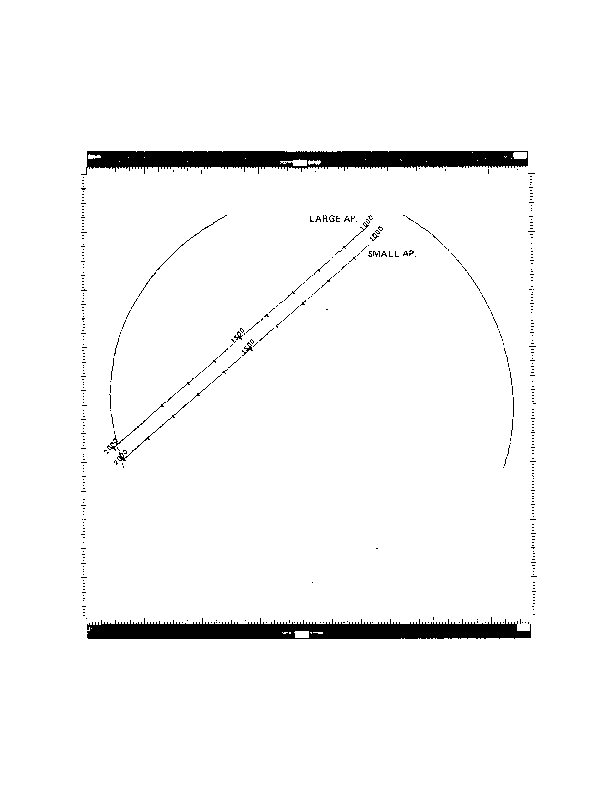 Figure 2-10.
Representation of the Low Dispersion Spectral Format
in the SWP Camera, Both Apertures
Figure 2-10.
Representation of the Low Dispersion Spectral Format
in the SWP Camera, Both Apertures
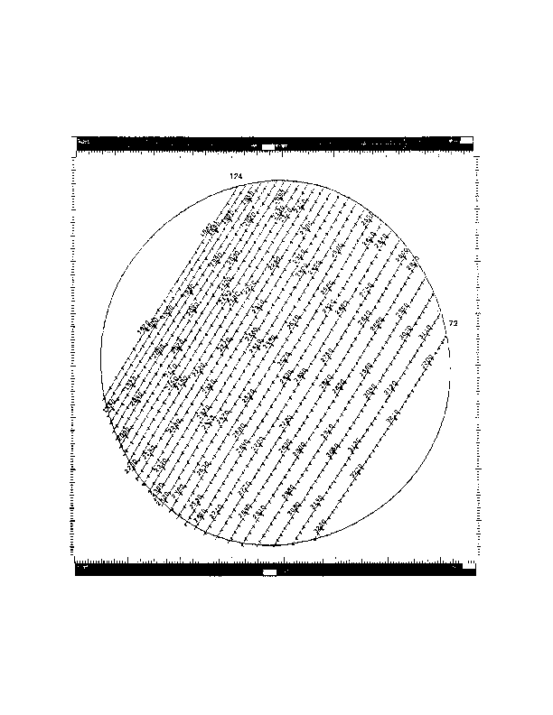 Figure 2-11.
Schematic Representation of the Echelle (High Dispersion)
Spectral Format in the Long Wavelength Redundant (LWR) Camera,
Small Aperture (Even Orders From 124 to 72)
Figure 2-11.
Schematic Representation of the Echelle (High Dispersion)
Spectral Format in the Long Wavelength Redundant (LWR) Camera,
Small Aperture (Even Orders From 124 to 72)
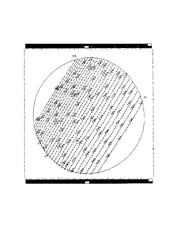 Figure 2-12.
Schematic Representation of the Echelle (High Dispersion)
Spectral Format in the LWR Camera, Small Aperture (Odd Orders
From 125 to 73)
Figure 2-12.
Schematic Representation of the Echelle (High Dispersion)
Spectral Format in the LWR Camera, Small Aperture (Odd Orders
From 125 to 73)
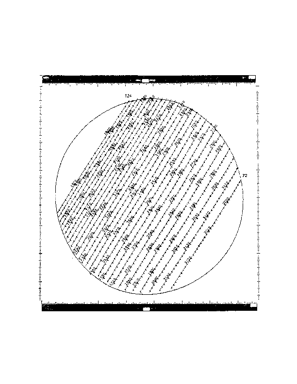 Figure 2-13.
Schematic Representation of the Echelle (High Dispersion)
Spectral Format in the LWR Camera, Large Aperture (Even
Orders From 124 to 72)
Figure 2-13.
Schematic Representation of the Echelle (High Dispersion)
Spectral Format in the LWR Camera, Large Aperture (Even
Orders From 124 to 72)
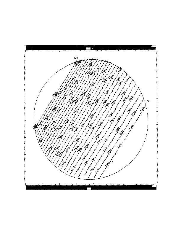 Figure 2-14.
Schematic Representation of the Echelle (High Dispersion)
Spectral Format in the LWR Camera, Large Aperture (Odd Orders
From 125 to 73)
Figure 2-14.
Schematic Representation of the Echelle (High Dispersion)
Spectral Format in the LWR Camera, Large Aperture (Odd Orders
From 125 to 73)
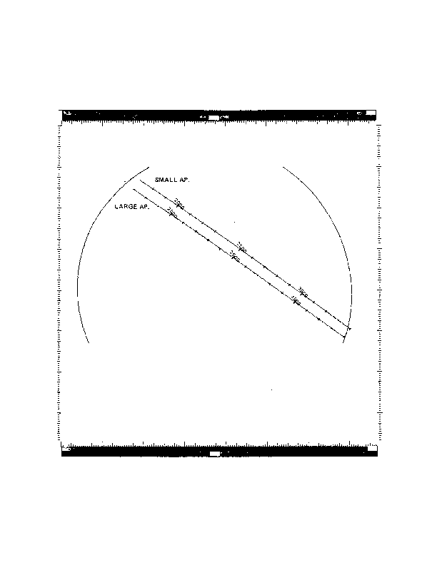 Figure 2-15.
Schematic Representation of the Low Dispersion Spectral Format
in the LWR Camera, Both Apertures
Figure 2-15.
Schematic Representation of the Low Dispersion Spectral Format
in the LWR Camera, Both Apertures
The long and short wavelength IUE spectrographs each have two entrance
apertures: a small aperture (nominal 3-arcsec diameter circle) and a large aperture
(nominal 10 arcsec by 20 arcsec slot). A compilation of the best available
determinations of various dimensions relating to the sizes and separations of the
small and large apertures in each spectrograph is contained in Panek (1982a).
Although the various methods available for determining the fundamental dimensions do
not always yield results which agree to within the limits set by the internal
consistency of each, the IUE Three Agency Coordination Meeting in May 1981 adopted
recommended values for certain dimensions, which are presented in Table
2-1. In
addition to listing these officially adopted dimensions, Panek (1982a) lists several
other derived quantities of interest, which are presented in Table
2-2.
Some of these fundamental quantities in Tables 2-1 and 2-2 differ from the older official values published in Bohlin et al. (1980) and presented in Versions 1.0 and 1.1 of this document. For the purposes of image processing, we continue to utilize the previously quoted plate scale of 1.525 ± 0.01 arcsec/pixel (Bohlin et al. 1980). Coupled with the known separation of the large and small apertures (approximately 40 arcsec in the short wavelength spectrograph and 41 arcsec in the long wavelength spectrograph) and the known geometrical orientation of the apertures (see the discussion of Figures 2-16 through 2-18 below), this implies the aperture separations in the image line and sample directions given in Table 2-3. Prior to 6 August 1979 for the LWR and SWP, and prior to 21 September 1982 for the LWP, different offset values were used in IUESIPS (see Turnrose et al. 1979; Turnrose and Harvel, 1982; Turnrose, 1983; see also Section 6.2.3).
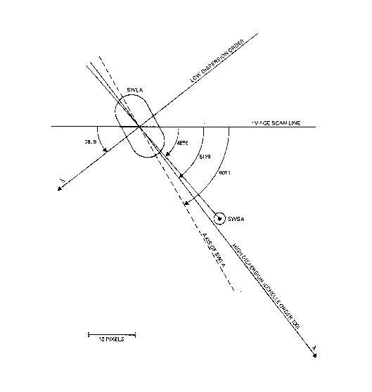
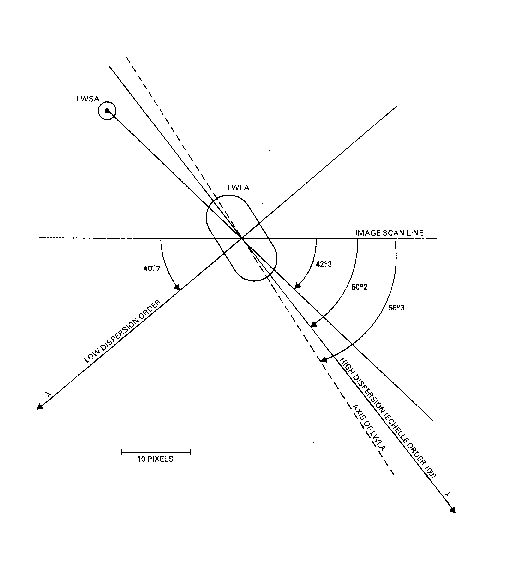
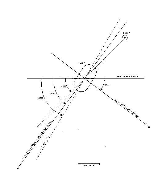
The geometry of the two entrance apertures in relation to the image scan lines and the high and low resolution dispersion directions is shown in Figures 2-16 through 2-18 for the SWP, LWP, and LWR cameras. These figures are drawn in the geometrically corrected frame of reference. Note particularly the fact that the separation of the short wavelength large aperture (SWLA) and the short wavelength small aperture (SWSA) is very nearly along the echelle dispersion direction. Therefore, short wavelength high dispersion images in which both apertures are exposed will result in nearly complete superposition of the large and small aperture spectra (with a wavelength offset). The separation of the long wavelength large aperture (LWLA) and the long wavelength small aperture (LWSA) is less coincident with the echelle dispersion direction, so that superposition of large and small aperture high dispersion spectra in the long wavelength spectrograph is not as serious as it is in the short wavelength spectrograph.
For the purposes of judging the extent and separation of the apertures in the spectral domain, the scales given in Table 2-4 (see Section 6 for their derivation) may be used in conjunction with the quantities in Tables 2-1 through 2-3. Note that in high dispersion the relevant scale for displacements along the dispersion is kilometers per second per pixel, whereas in low dispersion the relevant scale for displacements along the dispersion is angstroms per pixel. These scales are essentially constant across the entire tube face in each dispersion mode.
| Camera | Low Dispersion (Å /px-1) | High Dispersion (km/s-1/px-1) |
|---|---|---|
| LWP | 2.64 | 7.22 |
| LWR | 2.65 | 7.23 |
| SWP | 1.67 | 7.70 |
| SWR | TBD | TBD |
The in-flight resolution obtained with the IUE telescope/spectrograph/camera system has been sporadically studied. By Three-Agency agreement a joint program to summarize and codify the existing studies and identify further investigations needed to produce a comprehensive report on the point spread function (PSF) of IUE Spectra is now in progress (see Imhoff, 1983 and 1984a; Cassatella, Barbero, and Benvenuti 1983). The salient results of the studies are presented below; see also Holm (1982).
The results of Boggess et al. (1978), Cassatella, Martin, and Ponz (1981), Cassatella and Martin (1982) and Imhoff (1982,1983, 1984a) indicate the following.
Measurements of the effective FWHM obtained with the new high
dispersion reduction software, which eliminates the explicit
geometric correction and samples the spectrum twice as frequently
as the old software, may be estimated from the small sample of Pt-
Ne data plotted in Bohlin and Turnrose (1982). From those data,
in SWP the FWHM is ~ 0.08 - 0.10 Å (~ 2.2 - 2.6 pixels) near
![]() = 1400 Å and
= 1400 Å and
![]() = 1490 Å. Imhoff (1984a) presents more extensive
new-software results (see Table
2-5) which indicate that the FWHM
values are rather similar to those obtained with the old software.
= 1490 Å. Imhoff (1984a) presents more extensive
new-software results (see Table
2-5) which indicate that the FWHM
values are rather similar to those obtained with the old software.
As for SWP, the plots in Bohlin and Turnrose (1982) may be used to
estimate FWHM obtained with the new reduction software: ~ 0.15 Å
near both
![]() = 1940 Å (3.2 pixels) and
= 1940 Å (3.2 pixels) and
![]() = 2430 Å (2.5 pixels).
= 1940 Å (3.2 pixels) and
= 2430 Å (2.5 pixels).
= 1940 Å (3.2 pixels) and
![]() = 2430 Å (2.5 pixels).
Imhoff (1984a) presents similar and more extensive results which
show that higher resolution is obtained with the new software than
with the old. Table
2-5
shows that the FWHM obtained with the new software is about 15 percent
less than that obtained with the old.
= 2430 Å (2.5 pixels).
Imhoff (1984a) presents similar and more extensive results which
show that higher resolution is obtained with the new software than
with the old. Table
2-5
shows that the FWHM obtained with the new software is about 15 percent
less than that obtained with the old.
| Order | Wavelength | SWP(old) | SWP(new) |
|---|---|---|---|
| 69 | 2000 Å | .19 Å | .19 Å |
| 76 | 1800 Å | .17 Å | .16 Å |
| 86 | 1600 Å | .13 Å | .12 Å |
| 106 | 1300 Å | .10 Å | .09 Å |
Studies relevant to the high dispersion PSF perpendicular to the dispersion include Schiffer (1980), Bianchi (1980), Cassatella, Martin, and Ponz (1981), and de Boer, Preussner, and Grewing (1982). Bianchi (1980) presents empirical fits to the high dispersion order profiles irrespective of camera. Her results are that the FWHM for order m is approximated by 7.23 - 0.04m pixels, where m is the order number, and that the overall order profile can be fitted by a combination of Gaussian and Lorentzian functions. Results of studies directed at specific cameras are summarized below.
The above results pertain to the old reduction software; the results of de Boer, Preussner, and Grewing (1982), utilizing custom reduction techniques, are systematically smaller by about 1-2 pixels.